
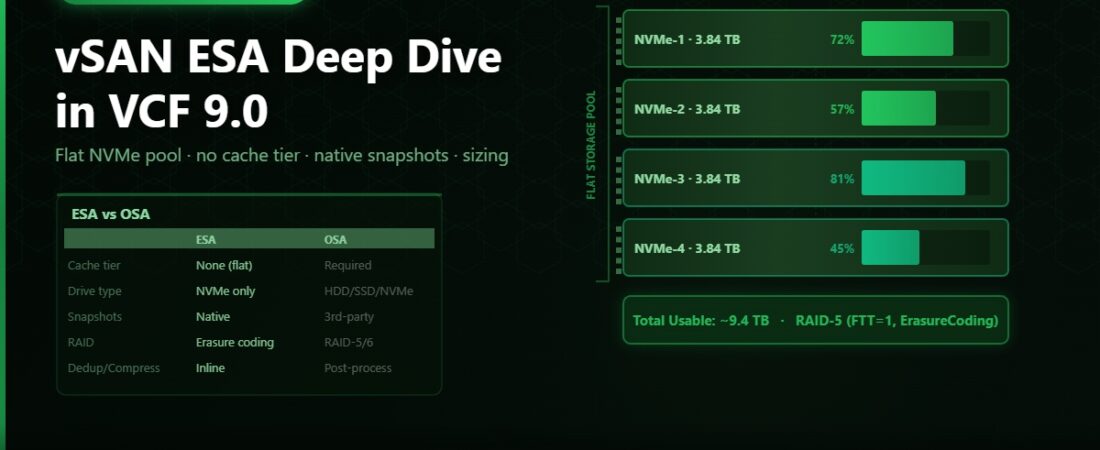
When I first started building vSAN clusters, the storage model was straightforward enough to sketch on a whiteboard in two minutes: cache tier, capacity tier, disk groups, one cache disk per group, capacity disks filling out the rest. That model worked well for a long time. Express Storage Architecture changes most of it, and if you’re coming to vSAN in VCF 9.0 without knowing what ESA actually is, the documentation can be disorienting.
This post covers ESA from the ground up — what changed, why it changed, and what it means for how you size, configure, and think about vSAN storage.
What OSA Was and Why It Had Limits
vSAN Original Storage Architecture (OSA) used a two-tier model. Each disk group contained one cache device — typically a fast NVMe or SSD — and between one and seven capacity devices. The cache tier served two purposes: write buffering and read cache. Writes landed in the cache device first and were destaged to capacity on schedule. Reads could be served from cache if the data was hot enough.
The design made sense when there was a meaningful performance gap between cache-tier devices and capacity-tier devices. If your capacity was spinning rust or early-generation SATA SSDs, having a fast NVMe cache in front made a real difference.
The problem is that high-performance NVMe drives closed that gap. When your capacity devices are fast NVMe SSDs, the cache tier stops being a meaningful accelerator and starts being a bottleneck. You’re forcing writes through an intermediate layer for no real benefit. You’re also limited in how you can grow: adding capacity means adding full disk groups, which means adding cache devices too, even if you don’t need more cache headroom.
ESA’s Flat Storage Pool
ESA eliminates the two-tier model entirely. There are no disk groups, no cache devices, no capacity devices. There’s a single flat pool of NVMe drives — all of them treated equally, all of them contributing to both throughput and capacity simultaneously.
The write buffering and read caching functions that used to live in the cache tier are now handled at a different level. ESA uses a log-structured storage engine that writes data in large sequential chunks regardless of the incoming I/O pattern, which makes the most of NVMe’s characteristics without needing a separate caching layer. Read performance comes from the raw speed of the NVMe devices in the pool, not from a cache hit ratio.
What this means practically is that adding a drive to an ESA cluster adds raw capacity and raw performance at the same time, in proportion. There’s no separate cache sizing exercise. You’re not calculating how many cache devices you need per disk group. You just add NVMe drives and the pool grows.
Hardware Requirements
ESA is NVMe-only. You cannot use SATA or SAS drives in an ESA cluster. This is a hard requirement, not a recommendation.
Broadcom publishes the vSAN ESA Hardware Compatibility Guide separately from the standard vSAN HCL. Not every NVMe drive that works with OSA is qualified for ESA — the qualification process for ESA is stricter because the storage engine relies more directly on specific NVMe characteristics like queue depth behaviour and write endurance. Always check the ESA HCL before procuring hardware or before upgrading an existing OSA cluster to ESA.
Minimum drive count per host for an ESA cluster is two NVMe drives. Practical deployments typically use four to eight drives per host depending on capacity and performance targets. The pool scales linearly — more drives means more IOPS and more capacity, with no cache-tier overhead eating into your effective capacity.
In VCF 9.0, when you deploy a workload domain and choose vSAN as the storage type, the VCF bring-up process will detect whether your hosts have an ESA-compatible configuration and offer ESA as the storage architecture. If your hardware isn’t on the ESA HCL, you’ll be using OSA. The choice happens at cluster creation time and cannot be changed after the fact without rebuilding the cluster.
Storage Policies in ESA
vSAN uses VM Storage Policies to define how data is protected and placed. ESA supports the same policy framework as OSA but with expanded options.
The core protection setting is Failures to Tolerate (FTT). With ESA, you can use either RAID-1 (mirroring) or RAID-5/6 (erasure coding) to meet your FTT requirement:
FTT=1 with RAID-1 means two copies of your data — you can lose one host and survive. FTT=1 with RAID-5 stores data with one parity stripe across four hosts — you can still lose one host, but you use 33% less space than RAID-1 for the same protection level. FTT=2 with RAID-6 gives you two-fault tolerance across six hosts with 50% overhead versus 67% for RAID-1 at FTT=2.
ESA also introduces RAID-5/6 with stretched clusters — something that wasn’t possible with OSA. In a two-site stretched cluster with ESA, you can run erasure coding across the sites rather than requiring full mirroring at each site.
One policy change specific to ESA: the Storage Policy Data Services (SPDS) option, which allows encryption at the policy level, snapshot offload to vSAN, and replication configuration — all defined in the storage policy and applied per-VM rather than cluster-wide. This is a significant change from OSA where encryption was an all-or-nothing cluster setting.
Snapshots: A Major Improvement
If you’ve ever worked with vSAN OSA and VM snapshots at scale, you know the pain. Traditional VMware snapshots use redo logs that chain off the base disk, and consolidating large snapshot chains on busy datastores has historically been slow and sometimes risky.
ESA introduces native vSAN snapshots that bypass the traditional redo-log mechanism entirely. Snapshots are handled by the vSAN storage engine itself using redirect-on-write, which means snapshot creation is near-instant regardless of VM size, and snapshot consolidation doesn’t cause the I/O spikes that traditional snapshots do. For environments that run backup solutions triggering frequent snapshots across many VMs, this alone is a compelling reason to move to ESA.
Sizing: How to Think About It
Without the cache tier to worry about, ESA sizing is cleaner. The main variables are raw capacity needed, the FTT policy you’re running, and the number of hosts in your cluster.
Effective capacity = (sum of all NVMe drive capacity across all hosts) divided by the overhead factor of your storage policy. For RAID-1 FTT=1 that factor is 2x. For RAID-5 FTT=1 across four hosts it’s approximately 1.33x. For RAID-6 FTT=2 across six hosts it’s approximately 1.5x.
As a rule of thumb for lab and small production ESA clusters: four hosts with four 2TB NVMe drives each gives you 32TB raw, which at RAID-5 FTT=1 delivers roughly 24TB usable before the vSAN overhead slack (Broadcom recommends keeping utilisation below 70% for performance headroom). That’s a reasonable starting point for a VCF workload domain.
For performance sizing, the good news is ESA is far more predictable than OSA. With OSA you had to model cache hit ratios and destage patterns. With ESA the bottleneck is simply the aggregate NVMe throughput of your pool. Add drives, add performance — linearly and predictably.
Monitoring vSAN ESA in VCF
The vSAN health and performance views in vCenter still work the same way — navigate to your vSAN cluster, go to the Monitor tab, and you’ll find health checks, capacity overview, and performance charts. ESA-specific views include the storage pool utilisation (replacing the disk group view from OSA) and the IOPS and latency charts broken down by individual NVMe device.
Aria Operations, if you’ve deployed it as part of your VCF stack, gives you more granular trending and capacity forecasting for vSAN ESA. The vSAN management pack in Aria Operations 8.x was updated to recognise ESA topology and shows pool-level metrics rather than the old disk group structure.
One thing to check regularly in an ESA cluster: drive health scores. Because the entire pool contributes to performance and protection simultaneously, a degraded drive has more impact than in an OSA cluster where a struggling capacity device is buffered by the cache tier. Keep an eye on the vSAN health dashboard for any drive health warnings and replace degraded devices promptly.
Can You Migrate from OSA to ESA?
Not in-place. There is no upgrade path from an existing OSA vSAN cluster to ESA. The storage architectures are fundamentally different at the on-disk format level.
The migration path is to build a new ESA cluster, vMotion your workloads to it, and decommission the OSA cluster. In a VCF environment this typically means adding a new workload domain with ESA-capable hosts and migrating VMs across before removing the old domain. It’s not a quick process, but it’s well-supported and the vMotion approach means zero downtime for the workloads themselves.
If you’re planning a new VCF deployment and have the option to choose hardware, spec ESA-compatible NVMe drives from the start. The architectural advantages — simplified sizing, better snapshot performance, linear scaling — are significant enough that it’s worth making ESA the default for any new VCF cluster.