If you’ve spent time with vSphere networking — standard switches, distributed switches, port groups, VLANs — and then you sit down with NSX for the first time, it can feel like someone moved all the furniture. Everything you knew still exists somewhere, but nothing is where you left it.
I went through that exact experience when I first started working with NSX in a VCF environment. So this post is the one I wish I’d had. We’re going to cover how NSX builds its logical network layer, what segments actually are, how traffic gets from a VM to the physical world, and where Tier-0 and Tier-1 gateways fit in. No assumption that you’ve touched NSX before.
Why NSX Exists in VCF
In a traditional vSphere environment, your networking is mostly physical. You configure port groups on a VDS, trunk VLANs down from your physical switches, and VMs land on whatever VLAN corresponds to their port group. The physical switch is doing the real work. VLANs are your network segments.
NSX changes the model. Instead of relying on physical VLANs to separate workloads, NSX builds an overlay network on top of your existing infrastructure. VMs communicate over tunnels — specifically Geneve-encapsulated tunnels — that NSX manages entirely in software. Your physical switches just see regular IP traffic between ESXi hosts. They don’t need to know anything about your VM workload topology.
This matters in VCF for a few reasons. You can spin up new network segments without touching your physical switches. You can stretch segments across sites without spanning VLANs across a WAN. You get a distributed firewall that enforces policy at the VM’s virtual NIC regardless of what network it’s on. And you get centralised routing that scales independently of your physical network design.
In VCF 9.0, NSX 9.0.x ships as a core component of both the management domain and workload domains. You don’t choose whether to use it — it’s there, and your workloads run on top of it.
Transport Nodes and Transport Zones
Before segments make sense, you need to understand two concepts: transport nodes and transport zones.
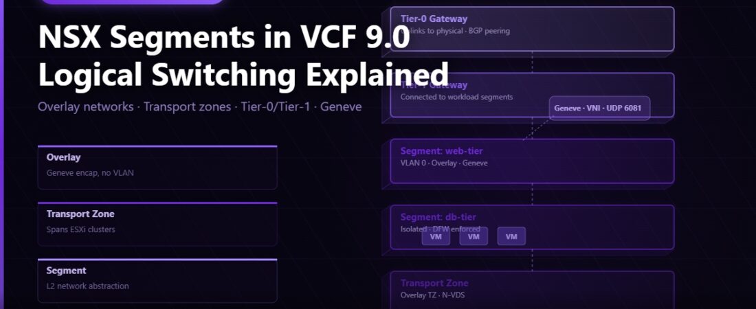
A transport node is any host that participates in the NSX overlay. In VCF, your ESXi hosts become NSX transport nodes when NSX is deployed on them. Each transport node runs an NSX kernel module that handles the Geneve tunnel encapsulation and decapsulation. From the physical network’s perspective, tunnel traffic between transport nodes is just regular UDP traffic on port 6081.
A transport zone defines which transport nodes can be part of the same logical network. If two hosts are in the same transport zone, their VMs can be on the same segment. If they’re not, they can’t. There are two flavours.
Overlay transport zones are for segments that use Geneve encapsulation — these are the segments your workload VMs typically live on. Traffic between VMs in an overlay segment stays in the tunnel until it needs to leave the overlay, at which point it exits through a gateway.
VLAN transport zones are for segments that map directly to a physical VLAN. These are used for infrastructure traffic: the TEP uplinks that carry your Geneve tunnels, the management network, and the uplinks on your Tier-0 gateways that connect to the physical routing infrastructure.
In a standard VCF 9.0 deployment, SDDC Manager sets up a default overlay transport zone and a default VLAN transport zone during NSX configuration. You don’t need to create these manually unless you’re building a non-standard topology.
What a Segment Actually Is
A segment is NSX’s equivalent of a port group combined with a network. When you create a segment, you’re creating a logical Layer 2 broadcast domain that exists in software. VMs connected to the same segment can communicate directly at Layer 2, regardless of which physical host they’re running on.
In NSX Manager, creating a basic segment looks like this: give it a name, pick a transport zone (almost always the overlay transport zone for workload segments), optionally assign a subnet if you want NSX to do distributed routing, and you’re done. There’s no VLAN ID to configure, no trunk port to set up on a physical switch, no port group to create on a VDS. The segment just exists across all the hosts in that transport zone.
When you connect a VM to an NSX segment, you’re connecting it to an NSX logical port. That port sits on the NSX logical switch (the segment), and NSX handles getting traffic from that VM to any other VM on the same segment — on the same host or across hosts — using the Geneve tunnel.
In vCenter, NSX segments appear as standard distributed port groups with an NSX label. You can connect VMs to them from the vSphere Client exactly like any other port group. The underlying mechanics are completely hidden from vCenter.
Where Traffic Actually Flows
Let’s say VM-A on Host-1 wants to talk to VM-B on Host-2. Both are on the same NSX overlay segment.
VM-A sends a frame destined for VM-B’s MAC address. The NSX kernel module on Host-1 looks up VM-B’s location in the distributed control plane — it knows which host VM-B is on and what IP is the Tunnel Endpoint for that host. It wraps the original frame in a Geneve header and sends it as a UDP packet from Host-1’s TEP IP to Host-2’s TEP IP. Host-2’s NSX kernel module receives the packet, strips the Geneve header, and delivers the inner frame to VM-B. From VM-A and VM-B’s perspective, they’re on the same switch.
The physical switch between Host-1 and Host-2 sees a UDP packet between two host IPs. It doesn’t know about the VMs. It doesn’t need to know about the segment. There are no VLAN trunks involved in that segment traffic at all.
When VM-A needs to reach something outside the overlay — another VLAN, the internet, an on-premises network — traffic goes up through a Tier-1 gateway and then a Tier-0 gateway, which is where the overlay meets the physical routing world.
Tier-1 and Tier-0 Gateways
NSX routing happens in gateways, not on traditional routers. There are two types and they work together.
A Tier-1 gateway is a logical router that connects to your segments. You attach segments to a Tier-1, give each segment an interface with a gateway IP, and the Tier-1 handles routing between those segments. It also advertises the segment subnets up to the Tier-0 gateway so those subnets are reachable from outside the overlay. Tier-1 gateways run as distributed logical routers — the routing happens in the kernel of each ESXi host, not in a centralised VM. Traffic between two VMs on segments attached to the same Tier-1, running on the same host, never leaves that host. It’s routed in the hypervisor kernel.
A Tier-0 gateway is the border between the NSX overlay and the physical network. It has uplinks connected to your physical routers via VLAN segments, and it runs BGP or static routing to exchange routes with the physical infrastructure. Subnets from your Tier-1 gateways propagate up to the Tier-0, which then advertises them to your physical routers. Return traffic follows the same path in reverse.
In a VCF 9.0 environment, the Tier-0 gateway for the management domain is deployed by SDDC Manager during the bring-up process. What you will build manually are Tier-1 gateways and segments for your workload domains as you start deploying actual workloads.
Creating a Workload Segment: What It Looks Like
Here’s the sequence I follow when I need a new network segment for a workload in VCF. This assumes NSX is already deployed and you have a working Tier-0 and at least one Tier-1 in place.
Log in to NSX Manager and navigate to Networking > Segments, then click Add Segment. Give the segment a meaningful name — I use a convention like seg-workload-web-192168100 so the name carries the subnet information. Set the Connected Gateway to your Tier-1 and the Transport Zone to your overlay transport zone. Under Subnets, add the gateway address in CIDR notation, for example 192.168.100.1/24. NSX uses that IP as the default gateway for VMs on this segment.
Save the segment. Within about 30 seconds it’s realised across all transport nodes in that transport zone. Go to vCenter, find your VM, edit its network adapter, and the new segment appears in the list alongside your other port groups. Connect the VM to it, and routing works immediately. No switch config. No VLAN provisioning request. The whole thing takes under two minutes once NSX is running.
Mistakes I’ve Seen (and Made)
The most common one is connecting a segment to a Tier-1 that isn’t connected to a Tier-0. The segment works — VMs on it can reach each other — but there’s no route outside. VMs ping each other fine, can’t reach anything else, and the troubleshooting path isn’t obvious until you know the gateway hierarchy.
Another one: putting Tier-0 uplinks on an overlay segment. Your Tier-0 connects to the physical routers over a VLAN, and that uplink segment needs to be in the VLAN transport zone, not the overlay transport zone. I’ve seen someone spend an afternoon on this — BGP sessions wouldn’t establish, everything looked correct in NSX Manager, and the problem turned out to be the transport zone mismatch on the uplink segment.
And always check TEP IP reachability when overlay tunnels aren’t forming. In VCF, SDDC Manager handles the TEP pool configuration during bring-up, but if you’re adding hosts manually or troubleshooting after a network change, the TEP VLAN and IP range are the first place to look. No TEP connectivity means no overlay, which means every segment on those hosts stops working.
What’s Next
This post covered the foundation — how NSX builds its overlay, what segments are, and how the gateway hierarchy connects it to the physical world. The next post goes deeper on the NSX Distributed Firewall: how it works, how it differs from a traditional perimeter firewall, and how to write your first DFW policies to control east-west traffic between your segments.